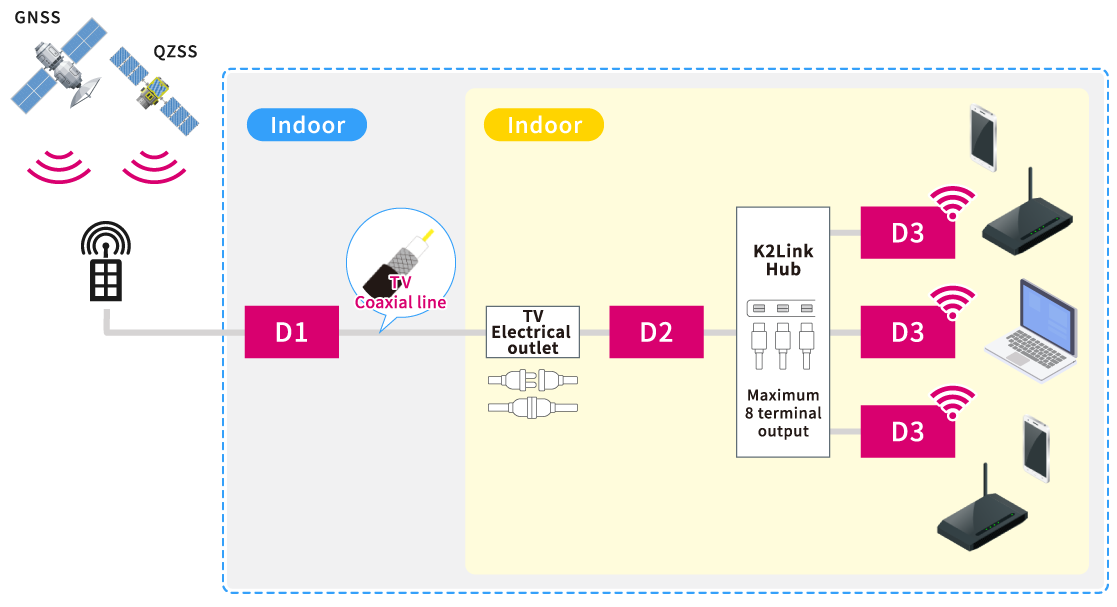
The system uses the pre-existing indoor CATV grid to transmit high-fidelity synchronized time data from GNSS satellites. The iPNT system consists of the D1 (installed on the rooftop), D2 (indoor), and D3 (the last piece in the chain, the iPNT transmitter).
Schematic diagram of iPNT system
iPNT terminals explained
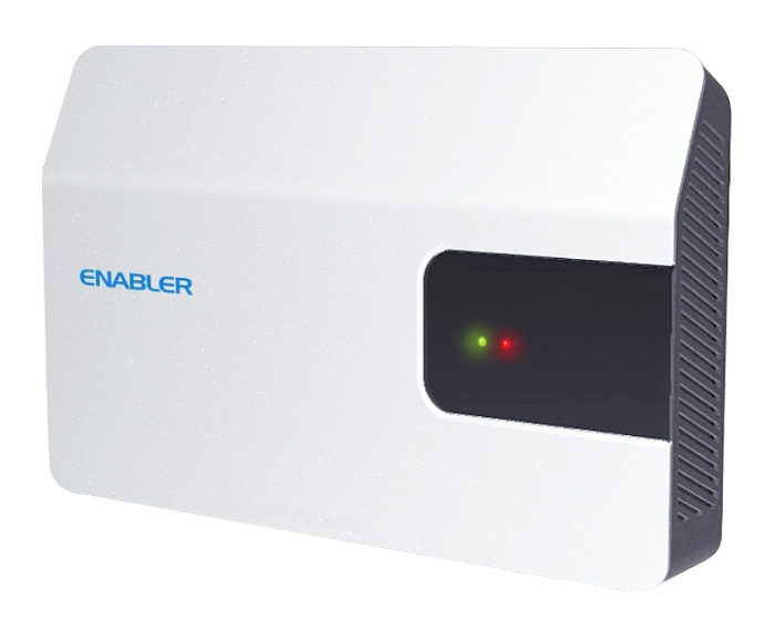
D1 exterior
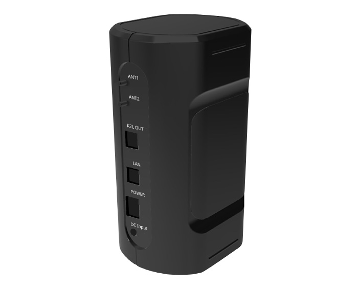
D2 reverse
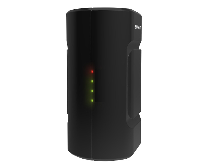
D2/D3 front
D3 reverse
Device
Functionality
D1
Receives signals from GNSS and converts the synchronized time signal to a frequency for transmission indoors.
D2
Receives a time signal from D1 and demodulates 1PPS. Also includes transmission functionality like D3, achieving a reduced formfactor.
D3
Receives data from D2 and calibrates timing before transmitting position and time. Also includes message transmission functionality.
K2Link Hub
This device is used to connect multiple D3 devices to a D2. Utilizes a dedicated cable.